Small-scale turbo compressors for more efficient take-off/landing and cruise of future aircraft
Airplanes play an important role in today’s worldwide transportation system. To handle the growing weight of freight and number of passengers, the plane size must increase while existing runways often cannot be extended. At the same time, there are increasing demands for reducing noise and increasing efficiency due to CO2 emissions and global warming. Prof. Zha and his team from the University of Miami conduct research in the area of active flow control concepts for ultra-high lift coefficient, the so-called Super-Lift condition, by energizing the boundary layer of airfoils. This principle allows for short take-off and landings, and enables drag reduction during cruise and, therefore, lower fuel consumption during long distance flights. The key technology providing this Super-Lift is an ultra-compact turbo compressor, which Celeroton has realized prototypes for wind tunnel testing.
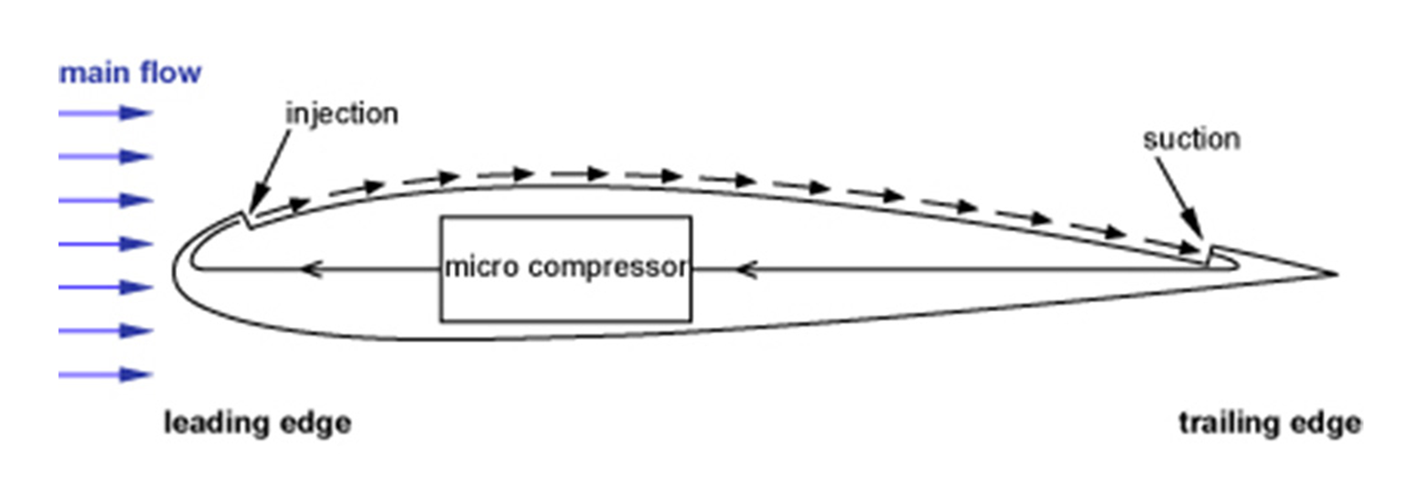
Figure 1: Compressor system boundaries
In recent CFD simulations from 2017, the research team at the University of Miami showed theoretically that it is possible to achieve Super-Lift conditions (SLC) by increasing the lift coefficient of airfoils over the so far known theoretical limit [Link]. This, however, is a new area of fluid mechanics and had to be proven in wind tunnel tests. Prof. Zha and his team’s task was to simulate the Super-Lift conditions with as close to realistic environmental conditions as possible. Thus, a micro compressor was needed that fits into the airfoil shape of the wing while complying with the requirements of sufficient mass flow and pressure increase.
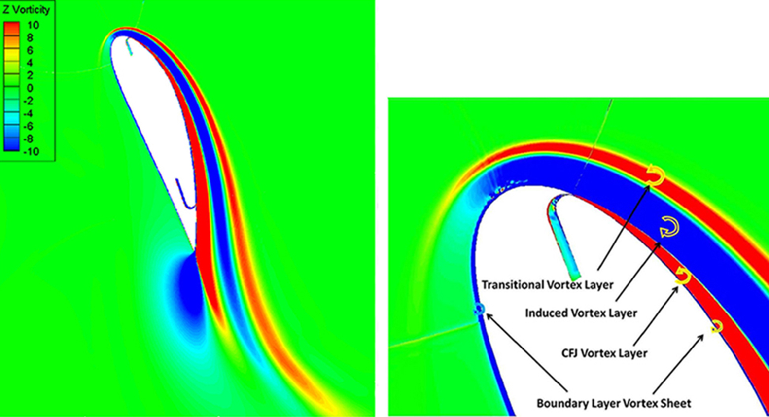
Figure 1 shows the principle of the active flow control system. The compressor draws a small mass flow near the trailing edge of the airfoil, pressurizes and therefore energizes it, and ejects it tangentially near the leading edge of the airfoil. The co-flow jet generates a counter clockwise vortex layer. Thus, the co-flow jet is the source inducing multiple vortex layers consisting of a complex pattern of four counter-rotating vortex layers (see Figure 2). The clockwise rotating vortex layers contribute to lift generation, while the counter-clockwise vortex layers contribute to thrust generation. The co-flow jet provides energy to resist the extremely high adverse pressure gradient, keeping the flow attached at very high angles of attack (AoA). For further information, please see [Link].
Figure 2: Vorticity contour for the CFJ6421-SST016-SUC053-INJ009 airfoil
The micro compressor’s role is to generate the airflow needed for the co-flow jet. This compressor, supplying an air mass flow in the range from 10 to 80 g/s at pressure ratios between 1.03 and 1.4, is custom specific. The aerodynamic design was carried out by PCA Engineers, a UK-based engineering consultancy specializing in turbomachinery design and analysis and turbomachinery design software. The requirements for the compressor performance were extracted from the CFD simulations carried out by University of Miami. Celeroton was responsible for the mechanical and electrical motor design as well as the manufacture and testing of the compressors. “The aerodynamic design of the compressors presented some fairly unique and interesting challenges”, says Dr. Chris Robinson, Managing Director of PCA Engineers, “and Celeroton’s innovative electro-mechanical design and attention to detail in manufacturing were central to the success of this compact design at such small scale.”
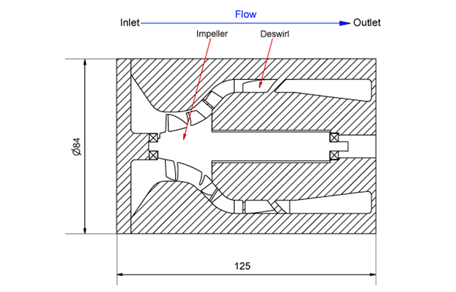
Applying PCA’s predictions of the aerodynamic performance map, Celeroton designed a 2 kW compressor fitting within a cylinder 125 mm in length and 84 mm in diameter, Figure 3. The absence of a water cooling system in the wing, in conjunction with the requirement for high power density, forced Celeroton to explore new designs for cooling the motor. The motor is therefore integrated into the flow channel, utilizing the main compressor airflow for cooling the motor while using the deswirl vanes both for reducing the swirl component of velocity and as cooling fins. To maintain sufficient ball bearing life for the prototype compressors, thrust compensation has been applied. “Challenging requirements motivate new approaches. This project allowed us to widen our horizon and to push the technical limits“, says Dr.-Ing. Fabian Dietmann, head of the Turbomachinery and Motor Group at Celeroton.
Figure 3: Sectional view of the custom turbo compressor (in mm).
Within the study by the University of Miami, in total five compressors are used for the wind tunnel tests. Each compressor is operated by its own converter. However, the energized boundary layer should be constant over the airfoil span. Therefore, Celeroton’s master-slave configuration of the standard converter CC-230-3500 was used, where only one – the master converter – is externally controlled by a PC, while the other slave converters follow the master converter’s command. These off-the-shelf converters are powered at 220 VAC, 60 Hz and are well-suited for test rig measurements. “The compact design and high efficiency allows us to validate our simulations”, says Prof. Zha from the University of Miami, “the easy-to-control converters make testing at different operating points very efficient”.
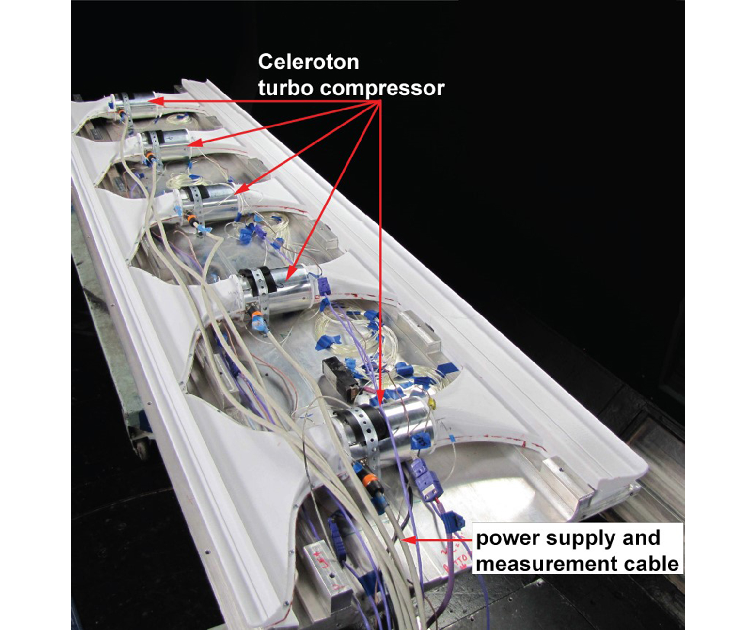
Figure 4 illustrates the lab-tested airfoil (adapted CFJ-NACA-6421 profile) without cover showing five compressors integrated. In this test setup, besides the compressors and supply cables, a range of instrumentation is attached for e.g. temperature, pressure and mass flow measurements. The next steps in the Super-Lift roadmap is the in-flight testing of the co-flow system, including onboard compressor systems.
Figure 4: Photo of the tested CFJ-NACA-6421 airfoil with five micro-compressors embedded