Application examples of the magnetic bearing CM-AMB-400 motor for optical applications
High speed rotating elements, such as disc shaped rotors crossing a beam, infrared and X-ray choppers; diffusor-discs in interferometers; mirrors in high-speed cameras or laser systems, are used to deflect a beam. The modular assembly of the magnetic bearing motor CM-AMB-400 allows the use of an application specific rotor. The concept of the magnetic bearing motor is such that a beam can be guided in radial or axial direction to the rotor to be deflected or chopped by the rotation.
By controlling the motor CM-AMB-400 with the controller CC-AMB-1500 a chopping frequency stability of better than +/- 0.03% can be achieved. The speed control algorithm allows for synchronisation of the rotational position of the disc with the beam frequency.
The synchronous rotor displacements are in the range of tenth of micrometres depending on the rotor geometry, whereas the asynchronous rotor displacements are controlled to the micrometre range.
Possible beam guidance in chopper-applications
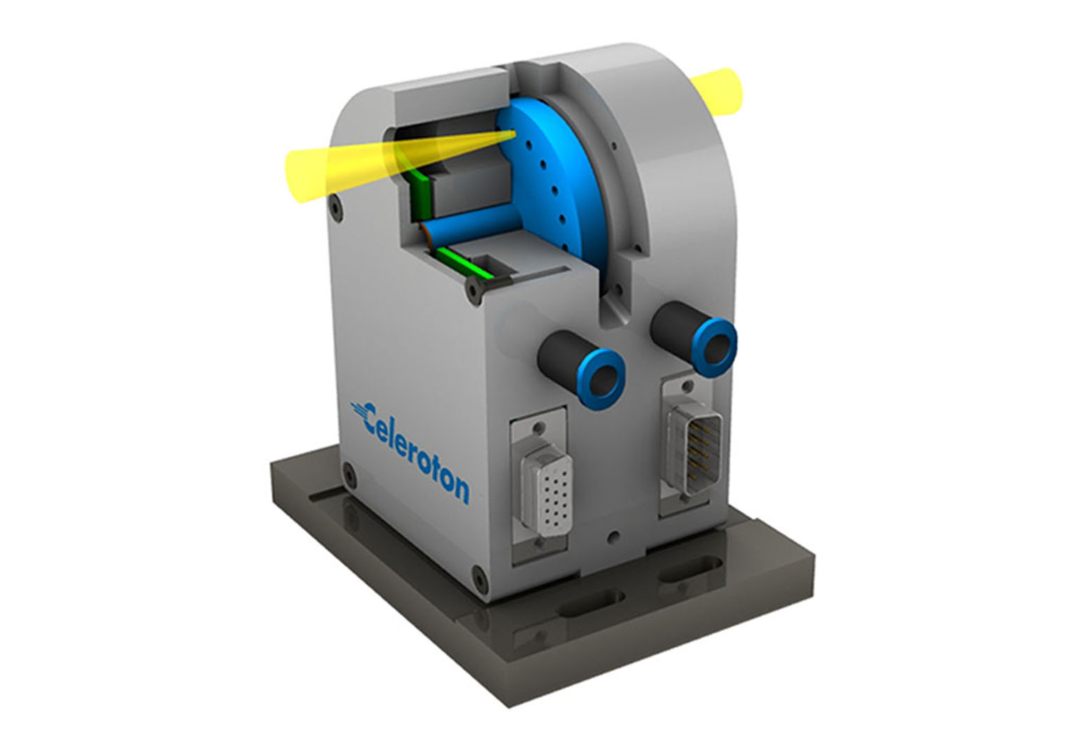
In a classical chopper-disc, the holes are placed in the axial direction. To realize such an application with the CM-AMB-400, its stator has holes in axial direction to guide the beam along the rotational direction (see picture 1). The minimal distance from the rotational axis is 12.5 mm, whereas the maximum distance can be application specific.
Picture 1: Classical chopper-disc with axial holes in the rotor
Instead of bores in the rotor, an axial beam can also go through the hole in the stator on the rotating surface treated disc which modifies the beam, as for example in an interferometer.
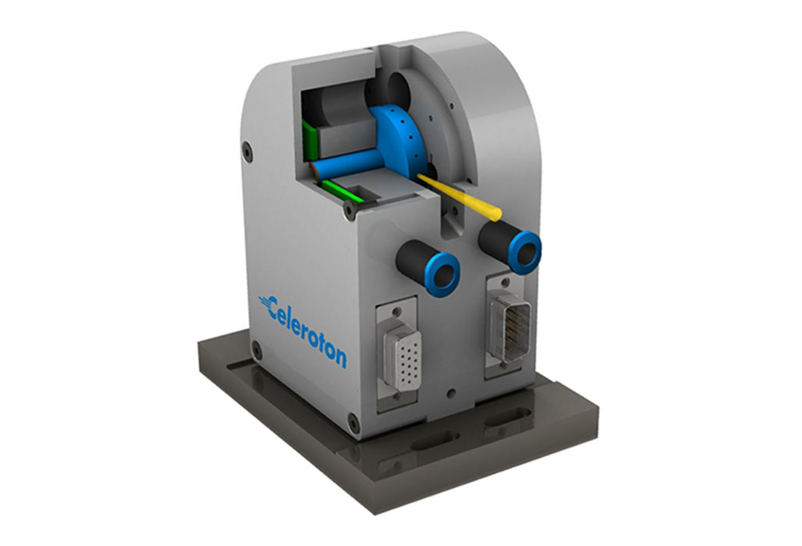
By decreasing the rotor diameter further, thus increasing the speed, the holes in the rotor can also be placed in radial direction. For this concept, the stator has the respective openings (see picture 2).
Picture 2: Chopper-disc with radial holes in the rotor
Reflecting surfaces on the rotor allow for maximizing the chopper frequency. Thereby, the beam is not interrupted completely, but instead redirected (see picture 3).
Picture 3: Chopper-disc with mirrors along the rotor circumference
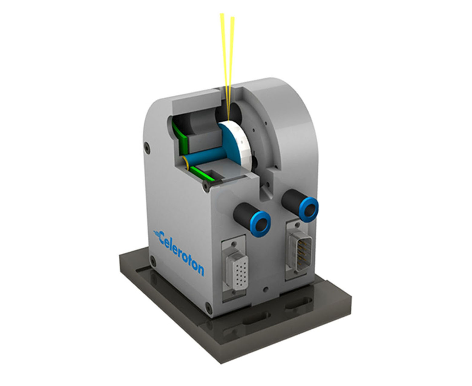
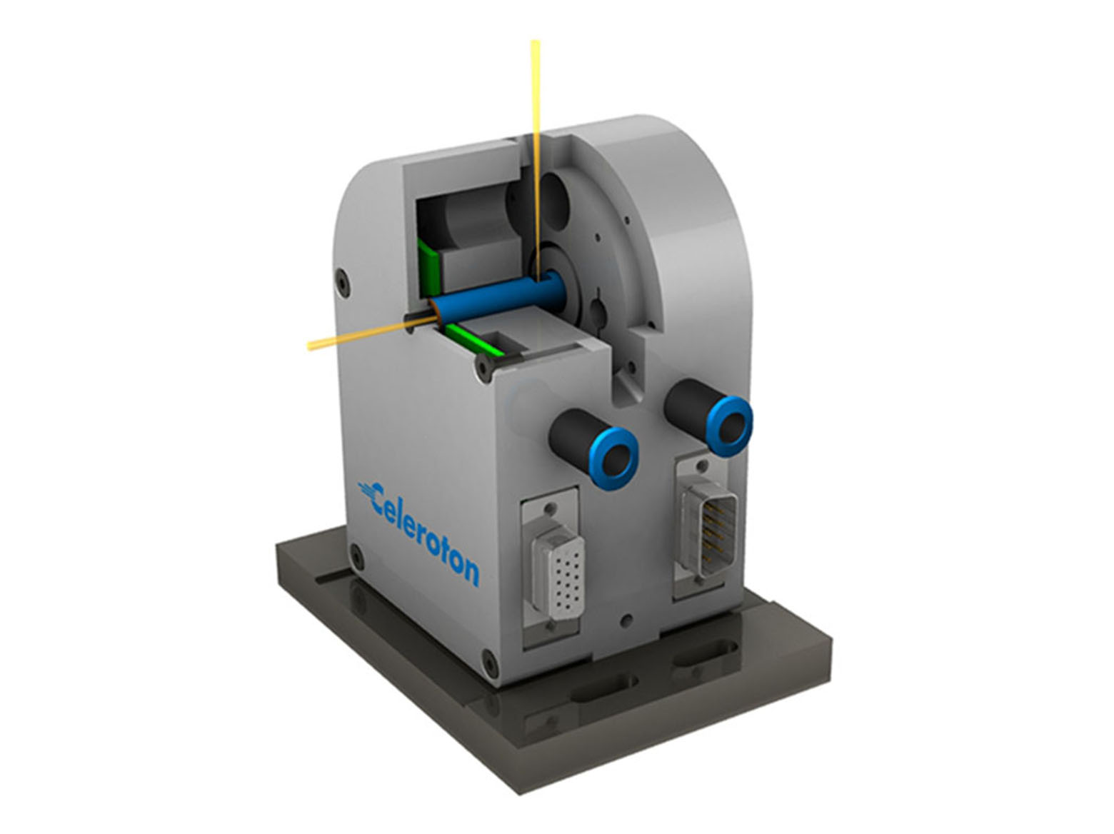
The CM-AMB-400 motor also offers the option to guide the beam through the rotor, onto or in close proximity to the rotational axis (see picture 4).
Picture 4: Rotor with axial bore for guidance of the beam onto the axis of rotation
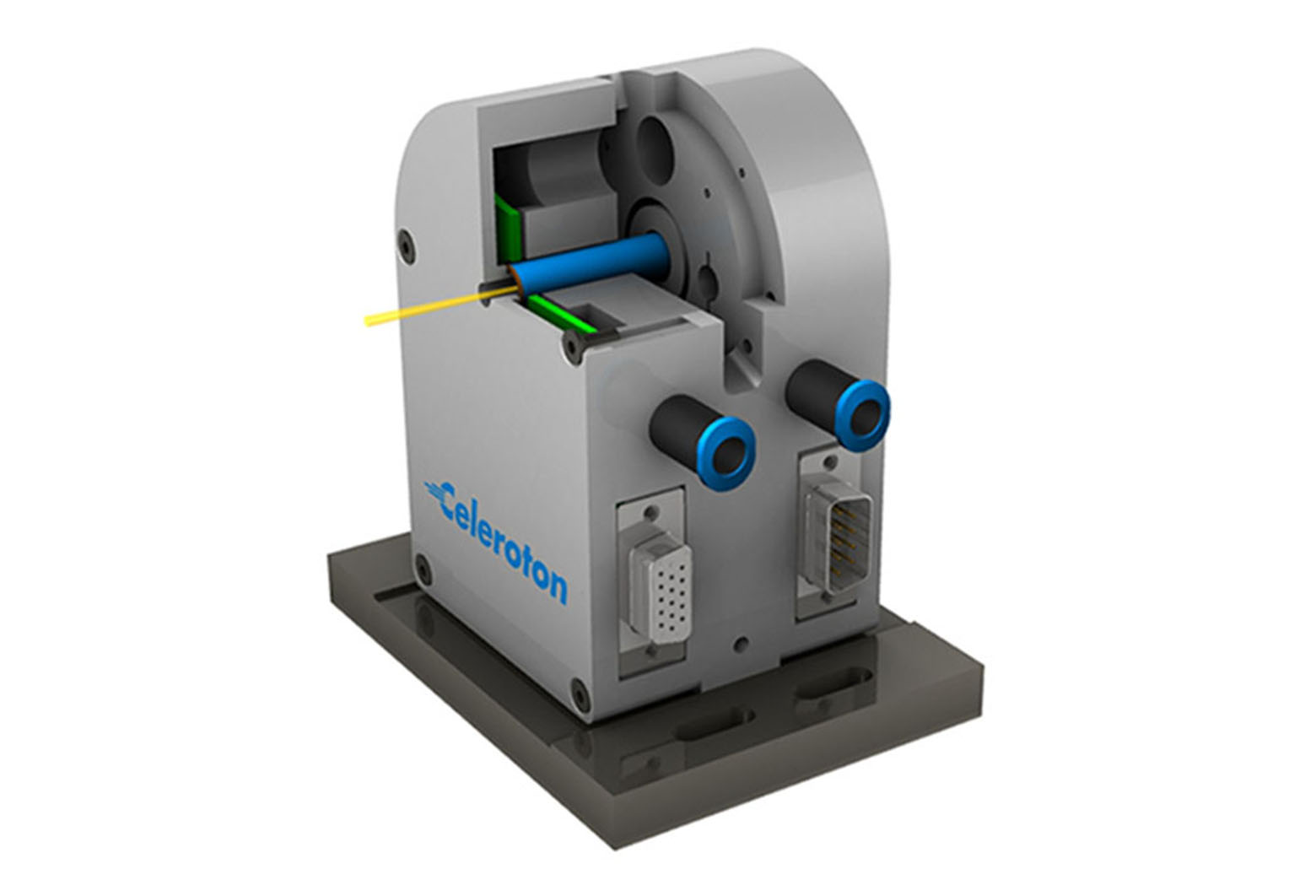
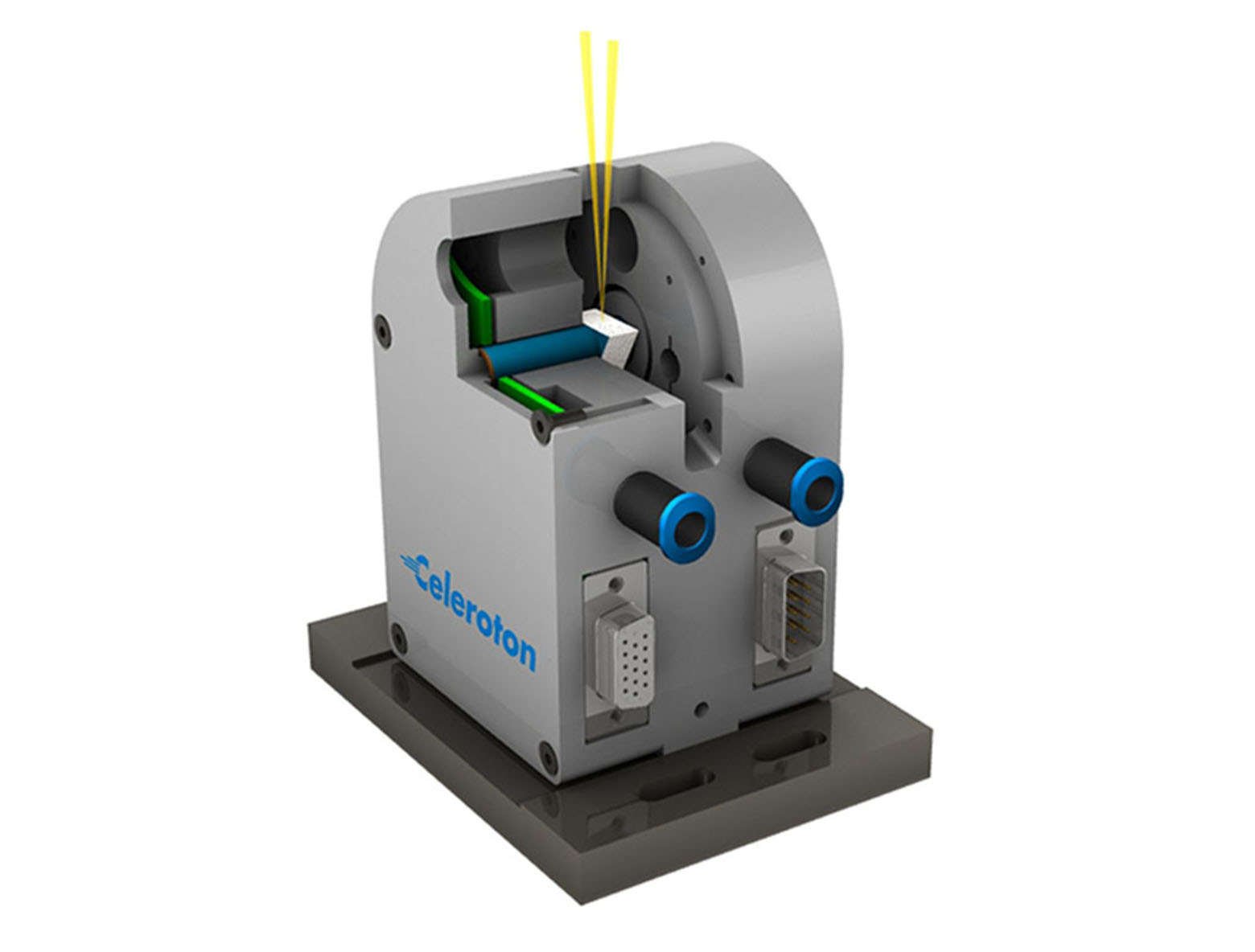
In the case where the beam shall not be guided completely through the rotor, a rotor with a bore on one side only can be used. Thereby, the beam is guided through the rotor in the axial direction and deflected by 90° with a mirror in the centre of the rotor, which radiates it radially out of the rotor (see picture 5).
Picture 5: Rotor with axial bore on one side only and a mirror in the centre to deflect the beam.
Possible beam guidance for applications with mirrors
In the classical way, rotors with mirrors are classified as a prism. Thereby two-sided, three-sided, up to n-sided prism are possible. In these applications, the beam comes in radially and is deflected in the radial direction. The axial length of the prism can be chosen based on the application. An example of a three-sided prism is shown in picture 6.
Picture 6: Mirror rotor with three-sided prism